Lincoln Aviator: Exterior Lighting / Removal and Installation - Stoplamp Switch
Removal
NOTE: Removal steps in this procedure may contain installation details.
-
Release the push pin and remove the drivers side insulation panel.
-
Remove the bolts.
Torque: 28 lb.in (3.2 Nm)
-
Remove the nut.
Torque: 22 lb.in (2.5 Nm)
-
Disconnect the electrical connector.
-
Remove the bolts.
.jpg) |
-
Disconnect the stoplamp switch electrical connector.
.jpg) |
-
NOTICE: Do not press, pull or otherwise move the brake pedal while installing the stoplamp switch and cruise control deactivation switch. Install these switches with the booster push rod attached to the brake pedal and with the brake pedal in the at-rest position. Installing these switches with the brake pedal in any other position results in incorrect adjustment and damages the switches.
Rotate the stoplamp switch clockwise approximately one-eighth turn to remove the stoplamp switch.
.jpg) |
Installation
-
NOTICE: Do not press, pull or otherwise move the brake pedal while installing the stoplamp switch and cruise control deactivation switch. Install these switches with the booster push rod attached to the brake pedal and with the brake pedal in the at-rest position. Installing these switches with the brake pedal in any other position results in incorrect adjustment and damages the switches.
To install, reverse the removal procedure.
 Removal and Installation - Reversing Lamp
Removal
NOTE:
Removal steps in this procedure may contain installation details.
Remove the liftgate trim panel.
Refer to: Liftgate Trim Panel (501-05 Interior Trim and Ornamentation, Removal and Installation)...
 Removal and Installation - Rear Lamp Fade Control Module
Removal
NOTE:
Removal steps in this procedure may contain installation details.
Remove the LH loadspace trim panel.
Refer to: Loadspace Trim Panel (501-05 Interior Trim and Ornamentation, Removal and Installation)...
Other information:
Lincoln Aviator 2020-2026 Owners Manual: Returning Your Vehicle to Normal Mode
Once it is safe to do so, reconnect the negative, black, battery cable to the battery. Apply the parking brake.Note: If the vehicle battery is dead, you could require an external power source to apply the parking brake. Fully apply the brake pedal and hold, do not release...
Lincoln Aviator 2020-2026 Service Manual: General Procedures - Transport Mode Deactivation
Deactivation NOTE: After vehicle build, some vehicle modules are set in Transport mode including the IPC and the BCM. Transport mode reduces battery drain during longer periods where the vehicle is not used. While in transport mode, the IPC displays TRANSPORT MODE CONTACT DEALER in the message center...
Categories
- Manuals Home
- Lincoln Aviator Owners Manual
- Lincoln Aviator Service Manual
- Changing the Front Wiper Blades - Vehicles With: Heated Wiper Blades
- Description and Operation - Body and Frame
- Description and Operation - Jacking and Lifting
- New on site
- Most important about car
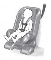
Child Seats

Use a child restraint (sometimes called an infant carrier, convertible seat, or toddler seat) for infants, toddlers and children weighing 40 lb (18 kg) or less (generally four-years-old or younger).
Using Lap and Shoulder Belts
WARNING: Do not place a rearward facing child restraint in front of an active airbag. Failure to follow this instruction could result in personal injury or death.
