Lincoln Aviator: Battery, Mounting and Cables / Removal and Installation - Battery Monitoring Sensor
Removal
NOTE: When the battery is disconnected and connected, some abnormal drive symptoms may occur while the vehicle relearns its adaptive strategy. The vehicle may need to be driven to allow the PCM to relearn the adaptive strategy values.
NOTE: Removal steps in this procedure may contain installation details.
-
Release the clips and remove the battery access cover.
.jpg) |
-
NOTICE: Make sure the positive battery terminal cover is in position while removing the negative battery cable clamp to prevent damage from a short to the positive terminal.
NOTICE: Be careful not to damage the sensor when removing the terminal from the battery post. Do not pry on the terminals or component damage may occur.
NOTICE: Do not remove or install the battery cable nut while the battery monitor sensor is attached to the battery post as this causes damage to the sensor, connector, and possibly the battery post and case.
Loosen, but do not remove the nut and position the negative battery cable aside.
Torque: 48 lb.in (5.4 Nm)
.jpg) |
-
NOTICE: Make sure the battery cable terminal is properly positioned to the battery monitoring sensor before tightening the nut or component damage may occur.
-
Disconnect the battery monitoring sensor electrical connector.
-
Remove the nut and the battery monitoring sensor.
Torque: 80 lb.in (9 Nm)
-
Disconnect the battery monitoring sensor electrical connector.
.jpg) |
Installation
-
To install, reverse the removal procedure.
 Removal and Installation - Battery Current Sensor
Removal
NOTE:
Removal steps in this procedure may contain installation details.
Position the rear compartment storage cover upward...
 Removal and Installation - Battery Tray
Removal
NOTE:
Removal steps in this procedure may contain installation details.
Remove the battery.
Refer to: Battery (414-01 Battery, Mounting and Cables, Removal and Installation)...
Other information:
Lincoln Aviator 2020-2025 Service Manual: Removal and Installation - Third Row Seat Head Restraint
Special Tool(s) / General Equipment Interior Trim Remover Removal Remove the third row seat backrest cover. Refer to: Third Row Seat Backrest Cover (501-10C Third Row Seats, Removal and Installation). Remove the third row seat backrest foam pin-type retainers...
Lincoln Aviator 2020-2025 Service Manual: Removal and Installation - Generator - 3.0L EcoBoost
Removal NOTE: Removal steps in this procedure may contain installation details. Disconnect the battery. Refer to: Battery Disconnect and Connect (414-01 Battery, Mounting and Cables, General Procedures). Remove the air cleaner...
Categories
- Manuals Home
- Lincoln Aviator Owners Manual
- Lincoln Aviator Service Manual
- Tire Change Procedure
- Interior Lamps
- Opening and Closing the Hood
- New on site
- Most important about car
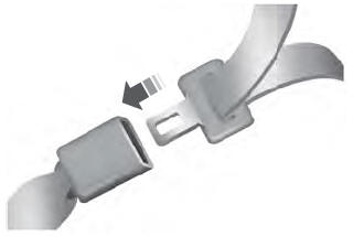
Fastening the Seatbelts
The front outboard and rear safety restraints in the vehicle are combination lap and shoulder belts.
Insert the belt tongue into the proper buckle (the buckle closest to the direction the tongue is coming from) until you hear a snap and feel it latch. Make sure that you securely fasten the tongue in the buckle.