
Lincoln Aviator: Roadside Emergencies / Fuel Shutoff
WARNING: If your vehicle has been involved in a crash, have the fuel system checked. Failure to follow this instruction could result in fire, personal injury or death.
Note: When you try to restart your vehicle after a fuel shutoff, the vehicle makes sure that various systems are safe to restart. Once the vehicle determines the systems are safe, then the vehicle allows you to restart.
Note: In the event that your vehicle does not restart after your third attempt, contact a qualified technician.
The fuel pump shutoff stops the flow of fuel to the engine in the event of a moderate to severe crash. Not every impact causes a shutoff.
Should your vehicle shut off after a crash, you may restart your vehicle.
If your vehicle has a key system:
- Switch off the ignition.
- Switch to start position.
- Switch off the ignition.
- Switch on the ignition to re-enable the fuel pump.
- If the vehicle does not start, repeat steps 1 through 4.
If your vehicle has a push button start system:
- Press START/STOP to switch off your vehicle.
- Press the brake pedal and START/STOP to switch on your vehicle.
- Remove your foot from the brake pedal and press START/STOP to switch off your vehicle.
- You can attempt to start the vehicle by pressing the brake pedal and START/STOP, or press START/STOP without pressing the brake pedal.
- If the vehicle does not start, repeat steps 1 through 4.
 Hazard Flashers
Note: The hazard flashers operate when the
ignition is in any position, or if the key is not
in the ignition. If used when the vehicle is not
running, the battery loses charge...
 Jump Starting the Vehicle
WARNING: Batteries normally
produce explosive gases which can cause
personal injury. Therefore, do not allow
flames, sparks or lighted substances to
come near the battery...
Other information:
Lincoln Aviator 2020-2026 Owners Manual: Using the Touchscreen
Status bar. Home screen. Clock. Outside air temperature. Feature bar. Status Bar Cell phone microphone muted. Audio system muted. Software update installed. Wi-Fi connected. Cell phone roaming. Text message received. Automatic crash notification system off...
Lincoln Aviator 2020-2026 Service Manual: General Procedures - Differential Fluid Level Check
Materials Name Specification Motorcraft® SAE 75W-85 Premium Synthetic Hypoid Gear LubricantXY-75W85-QL WSS-M2C942-A Check With the vehicle in NEUTRAL, position it on a hoist. Refer to: Jacking and Lifting (100-02 Jacking and Lifting, Description and Operation)...
Categories
- Manuals Home
- Lincoln Aviator Owners Manual
- Lincoln Aviator Service Manual
- Changing the Front Wiper Blades - Vehicles With: Heated Wiper Blades
- Drive Modes
- Garage Door Opener
- New on site
- Most important about car
Child Seats
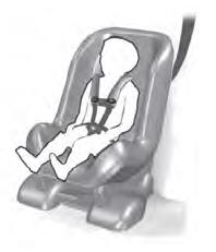
Use a child restraint (sometimes called an infant carrier, convertible seat, or toddler seat) for infants, toddlers and children weighing 40 lb (18 kg) or less (generally four-years-old or younger).
Using Lap and Shoulder Belts
WARNING: Do not place a rearward facing child restraint in front of an active airbag. Failure to follow this instruction could result in personal injury or death.
