Lincoln Aviator 2020-2025 Service Manual / Powertrain / Automatic Transmission / Automatic Transmission - 10-Speed Automatic Transmission – 10R60 / Description and Operation - Planetary Assembly
Lincoln Aviator: Automatic Transmission - 10-Speed Automatic Transmission – 10R60 / Description and Operation - Planetary Assembly
Planetary Gearset Exploded View
.jpg)
| Item | Description |
| 1 | Ring gear No. 1 |
| 2 | Sun gear No. 1 |
| 3 | Planetary carrier No. 1 |
| 4 | Sun gear No. 2 |
| 5 | Planetary carrier No. 2 |
| 6 | Ring gear No. 2 |
| 7 | Planetary carrier No. 3 |
| 8 | Sun gear No. 3 |
| 9 | Ring gear No. 3 |
| 10 | Shell and sun gear No. 4 |
| 11 | Ring gear No. 4 |
| 12 | Output shaft and planetary carrier No. 4 assembly |
| 13 | Cylinder (clutch and planetary container) |
The 10-speed transmission has 4 planetary gearsets. Each gearset consists of a ring gear, a sun gear and a carrier. The gear sets are numbered 1 through 4, from the front to the back of the transmission. There are several direct connections between the gearsets:
- Sun gears No. 1 and 2 are directly connected together with gear splines.
- Planetary carrier No. 1 and ring gear No. 4 are directly connected together with the cylinder (clutch and planetary container).
- Ring gear No. 2 and sun gear No. 3 are directly connected together with a shaft.
- Ring gear No. 3 and shell and sun gear No. 4 are directly connected together through the shell of the shell and sun gear No. 4.
 Description and Operation - Pump Assembly
Overview
Item
Description
1
Transmission fluid pump drive gear
2
Transmission fluid pump idler gear
3
Transmission fluid pump assembly
4
Transmission fluid filter
The
transmission fluid in the sump area at the bottom of the transmission
case flows through a transmission fluid filter to the pump assembly...
 Description and Operation - Transmission Fluid Auxiliary Pump
Item
Description
1
Transmission fluid auxiliary pump
2
Transmission fluid auxiliary pump tube
3
Transmission fluid auxiliary pump tube seal
4
Transmission fluid auxiliary pump tube O-ring
5
Transmission fluid auxiliary pump fluid inlet
10-speed
transmissions with the auto-start stop feature are equipped with a
transmission fluid auxiliary pump...
Other information:
Lincoln Aviator 2020-2025 Service Manual: Diagnosis and Testing - Engine Ignition
Diagnostic Trouble Code (DTC) Chart Diagnostics in this manual assume a certain skill level and knowledge of Ford-specific diagnostic practices.REFER to: Diagnostic Methods (100-00 General Information, Description and Operation). Diagnostic Trouble Code Chart Module DTC Description Action PCM P0300:00 Random Misfire Detected: No Sub Type Information GO to Pinpoint Test HD PCM P0301:00 Cylinder 1 Misfire Detected: No Sub Type Information GO to Pinpoint Test HD PCM P0302:00 Cylinder 2 Misfire Detected: No Sub Type Information GO to Pinpoint Test HD PCM P0303:00 Cylinder 3 Misfire Detected: No Sub Type Information GO to Pinpoint Test HD PCM P0304:00 Cylinder 4 Misfire Detected: No Sub Type Information GO to Pinpoint Test HD PCM P0305:00 Cylinder 5 Misfire Detected: No Sub Type Information GO to Pinpoint Test HD PCM P0306:00 Cylinder 6 Misfire Detected: No Sub Type Information GO to Pinpoint Test HD PCM P0307:00 Cylinder 7 Misfire Detected: No Sub Type Information GO to Pinpoint Test HD PCM P0308:00 Cylinder 8 Misfire Detected: No Sub Type Information GO to Pinpoint Test HD PCM P0313:00 Misfire Detected With Low Fuel: No Sub Type Information GO to Pinpoint Test HD PCM P0316:00 Misfire Detected On Startup (First 1000 Revolutions): No Sub Type Information GO to Pinpoint Test HD PCM P0325:00 Knock/Combustion Vibration Sensor A Circuit: No Sub Type Information GO to Pinpoint Test DG PCM P0327:00 Knock/Combustion Vibration Sensor A Circuit Low: No Sub Type Information GO to Pinpoint Test DG PCM P0328:00 Knock/Combustion Vibration Sensor A Circuit High: No Sub Type Information GO to Pinpoint Test DG PCM P032A:00 Knock/Combustion Vibration Sensor C Circuit: No Sub Type Information GO to Pinpoint Test DG PCM P032C:00 Knock/Combustion Vibration Sensor C Circuit Low: No Sub Type Information GO to Pinpoint Test DG PCM P032D:00 Knock/Combustion Vibration Sensor C Circuit High: No Sub Type Information GO to Pinpoint Test DG PCM P0330:00 Knock/Combustion Vibration Sensor B Circuit: No Sub Type Information GO to Pinpoint Test DG PCM P0332:00 Knock/Combustion Vibration Sensor B Circuit Low: No Sub Type Information GO to Pinpoint Test DG PCM P0333:00 Knock/Combustion Vibration Sensor B Circuit High: No Sub Type Information GO to Pinpoint Test DG PCM P033A:00 Knock/Combustion Vibration Sensor D Circuit: No Sub Type Information GO to Pinpoint Test DG PCM P033C:00 Knock/Combustion Vibration Sensor D Circuit Low: No Sub Type Information GO to Pinpoint Test DG PCM P033D:00 Knock/Combustion Vibration Sensor D Circuit High: No Sub Type Information GO to Pinpoint Test DG PCM P0351:00 Ignition Coil A Primary Control Circuit/Open: No Sub Type Information GO to Pinpoint Test JF PCM P0352:00 Ignition Coil B Primary Control Circuit/Open: No Sub Type Information GO to Pinpoint Test JF PCM P0353:00 Ignition Coil C Primary Control Circuit/Open: No Sub Type Information GO to Pinpoint Test JF PCM P0354:00 Ignition Coil D Primary Control Circuit/Open: No Sub Type Information GO to Pinpoint Test JF PCM P0355:00 Ignition Coil E Primary Control Circuit/Open: No Sub Type Information GO to Pinpoint Test JF PCM P0356:00 Ignition Coil F Primary Control Circuit/Open: No Sub Type Information GO to Pinpoint Test JF PCM P0357:00 Ignition Coil G Primary Control Circuit/Open: No Sub Type Information GO to Pinpoint Test JF PCM P0358:00 Ignition Coil H Primary Control Circuit/Open: No Sub Type Information GO to Pinpoint Test JF PCM P06B6:00 Internal Control Module Knock Sensor Processor 1 Performance: No Sub Type Information GO to Pinpoint Test DG PCM P06D1:00 Internal Control Module Ignition Coil Control Module Performance: No Sub Type Information GO to Pinpoint Test JF PCM P112A:00 Too Many Engine Starts During Factory/Transport Mode: No Sub Type Information GO to Pinpoint Test JB PCM P130D:00 Engine Knock/Combustion Performance - Forced Limited Power: No Sub Type Information GO to Pinpoint Test DG PCM P2300:00 Ignition Coil A Primary Control Circuit Low: No Sub Type Information GO to Pinpoint Test JF PCM P2301:00 Ignition Coil A Primary Control Circuit High: No Sub Type Information GO to Pinpoint Test JF PCM P2303:00 Ignition Coil B Primary Control Circuit Low: No Sub Type Information GO to Pinpoint Test JF PCM P2304:00 Ignition Coil B Primary Control Circuit High: No Sub Type Information GO to Pinpoint Test JF PCM P2306:00 Ignition Coil C Primary Control Circuit Low: No Sub Type Information GO to Pinpoint Test JF PCM P2307:00 Ignition Coil C Primary Control Circuit High: No Sub Type Information GO to Pinpoint Test JF PCM P2309:00 Ignition Coil D Primary Control Circuit Low: No Sub Type Information GO to Pinpoint Test JF PCM P2310:00 Ignition Coil D Primary Control Circuit High: No Sub Type Information GO to Pinpoint Test JF PCM P2312:00 Ignition Coil E Primary Control Circuit Low: No Sub Type Information GO to Pinpoint Test JF PCM P2313:00 Ignition Coil E Primary Control Circuit High: No Sub Type Information GO to Pinpoint Test JF PCM P2315:00 Ignition Coil F Primary Control Circuit Low: No Sub Type Information GO to Pinpoint Test JF PCM P2316:00 Ignition Coil F Primary Control Circuit High: No Sub Type Information GO to Pinpoint Test JF PCM P2319:00 Ignition Coil G Primary Control Circuit High: No Sub Type Information GO to Pinpoint Test JF PCM P2322:00 Ignition Coil H Primary Control Circuit High: No Sub Type Information GO to Pinpoint Test JF Global Customer Symptom Code (GCSC) Chart Diagnostics in this manual assume a certain skill level and knowledge of Ford-specific diagnostic practices...
Lincoln Aviator 2020-2025 Service Manual: Removal and Installation - Shock Absorber and Spring Assembly - Vehicles With: Air Suspension
Removal WARNING: Vent all air pressure from the air suspension system prior to disconnecting or removing any air suspension components. It is dangerous to remove air suspension components while under pressure. Failure to follow this instruction may result in serious personal injury...
Categories
- Manuals Home
- Lincoln Aviator Owners Manual
- Lincoln Aviator Service Manual
- Garage Door Opener
- Child Safety Locks
- Remove and Reinstall the Battery
- New on site
- Most important about car
Fastening the Seatbelts
The front outboard and rear safety restraints in the vehicle are combination lap and shoulder belts.
Insert the belt tongue into the proper buckle (the buckle closest to the direction the tongue is coming from) until you hear a snap and feel it latch. Make sure that you securely fasten the tongue in the buckle.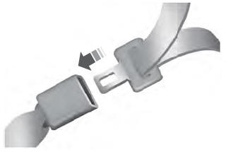
Copyright © 2025 www.liaviator2.com