Lincoln Aviator: Power Steering / Removal and Installation - Tie Rod
Special Tool(s) / General Equipment
| Boot Clamp Pliers |
Materials
| Name | Specification |
|---|---|
| Motorcraft® Premium Long-Life Grease XG-1-E1 |
ESA-M1C75-B |
Removal
NOTICE: When servicing inner tie rods, install a new bellows boot and clamps. The boots and clamps are designed to provide an airtight seal and protect the internal components of the steering gear. If the seal is not airtight, the vacuum generated during turning will draw water and contamination into the gear, causing failure of the steering gear components. Zip ties must not be used as they do not provide an airtight seal.
NOTICE: The inner ball joint grease is not compatible with water contamination. Do not allow water to become trapped in the grease or degradation and failure of the joint may occur.
NOTE: If the RH inner tie rod is being serviced, remove the LH outer tie rod end and bellows boot to access and hold the steering rack when loosening and tightening the inner tie rod.
-
Remove the tie rod end.
Refer to: Tie Rod End (211-02 Power Steering, Removal and Installation).
-
Remove the tie rod end jamb nut.
.jpg) |
-
If equipped.
Remove the underbody shield.
Refer to: Engine Front Undershield (501-02 Front End Body Panels, Removal and Installation).
-
-
Remove and discard the inner bellows boot clamp.
-
Remove and discard the outer bellows boot clamp.
-
Remove and discard the inner bellows boot clamp.
.jpg) |
-
NOTE: Move the bellows boot enough to gain access to the inner tie rod nut.
Position aside the bellows boot.
.jpg) |
-
NOTICE: Place the steering gear at the center position and hold the steering gear rack while loosening the tie rod. Use an appropriate-sized wrench on the flat/teeth of the rack to resist rotation and to prevent damage during removal of the tie rod.
Using an appropriate-sized wrench on the flat/teeth to hold the rack and an appropriate size crows foot wrench or open end wrench, remove and discard the tie rod.
.jpg) |
Installation
-
NOTICE: Place the steering gear at the center position and hold the steering gear rack while tightening the tie rod. Use an appropriate-sized wrench on the flat/teeth of the rack to resist rotation and to prevent damage during installation of the tie rod.
NOTE: The help of an assistant may be necessary to torque the RH tie rod.
Remove the tie rod.
Torque: 89 lb.ft (120 Nm)
.jpg) |
-
Apply the specified grease to the steering
gear-to-bellows boot mating surface and bellows boot groove on the
tie-rod.
Material: Motorcraft® Premium Long-Life Grease / XG-1-E1 (ESA-M1C75-B)
.jpg) |
-
-
Install the new steering gear bellows boot.
-
Install the new inner bellows boot clamp.
Use the General Equipment: Boot Clamp Pliers
-
Install the new outer bellows boot clamp.
-
Install the new steering gear bellows boot.
.jpg) |
-
If equipped.
Install the underbody shield.
Refer to: Engine Front Undershield (501-02 Front End Body Panels, Removal and Installation).
-
Thread the tie rod end jam nut onto the tie rod.
|
-
Install the tie rod end.
Refer to: Tie Rod End (211-02 Power Steering, Removal and Installation).
 Removal and Installation - Steering Gear Boot
Special Tool(s) /
General Equipment
Boot Clamp Pliers
Materials
Name
Specification
Motorcraft® Premium Long-Life GreaseXG-1-E1
ESA-M1C75-B
Removal
NOTICE:
The steering gear boots and clamps are designed to provide
an airtight seal and protect the internal components of the steering
gear...
 Removal and Installation - Tie Rod End
Special Tool(s) /
General Equipment
Tie Rod End Remover
Removal
NOTE:
Removal steps in this procedure may contain installation details.
Remove the wheel and tire...
Other information:
Lincoln Aviator 2020-2026 Owners Manual: Intelligent Oil-Life Monitor™
Your vehicle has an Intelligent Oil-Life Monitor that determines when you should change the engine oil based on how you use your vehicle. By using several important factors in its calculations, the monitor helps reduce the cost of owning your vehicle and reduces environmental waste at the same time...
Lincoln Aviator 2020-2026 Owners Manual: Towing a Trailer
WARNING: Towing trailers beyond the maximum recommended gross trailer weight exceeds the limit of your vehicle and could result in engine damage, transmission damage, structural damage, loss of vehicle control, vehicle rollover and personal injury...
Categories
- Manuals Home
- Lincoln Aviator Owners Manual
- Lincoln Aviator Service Manual
- USB Port and Power Point Locations
- Tire Change Procedure
- Anti-Theft Alarm
- New on site
- Most important about car
Child Seats
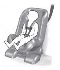
Use a child restraint (sometimes called an infant carrier, convertible seat, or toddler seat) for infants, toddlers and children weighing 40 lb (18 kg) or less (generally four-years-old or younger).
Using Lap and Shoulder Belts
WARNING: Do not place a rearward facing child restraint in front of an active airbag. Failure to follow this instruction could result in personal injury or death.