Lincoln Aviator: Supplemental Restraint System / Removal and Installation - Passenger Knee Airbag
Removal
.jpg) WARNING:
The following procedure prescribes critical repair steps
required for correct restraint system operation during a crash. Follow
all notes and steps carefully. Failure to follow step instructions may
result in incorrect operation of the restraint system and increases the
risk of serious personal injury or death in a crash.
WARNING:
The following procedure prescribes critical repair steps
required for correct restraint system operation during a crash. Follow
all notes and steps carefully. Failure to follow step instructions may
result in incorrect operation of the restraint system and increases the
risk of serious personal injury or death in a crash.
NOTE: Removal steps in this procedure may contain installation details.
-
Refer to: Pyrotechnic Device Health and Safety Precautions (100-00 General Information, Description and Operation)..jpg) WARNING:
Before beginning any service procedure in this
manual, refer to health and safety warnings in section 100-00 General
Information. Failure to follow this instruction may result in serious
personal injury.
WARNING:
Before beginning any service procedure in this
manual, refer to health and safety warnings in section 100-00 General
Information. Failure to follow this instruction may result in serious
personal injury.
-
Depower the SRS.
Refer to: Supplemental Restraint System (SRS) Depowering (501-20B Supplemental Restraint System, General Procedures).
-
Remove the glove compartment.
Refer to: Glove Compartment (501-12 Instrument Panel and Console, Removal and Installation).
-
Remove the retainers and lower the insulation panel.
.jpg) |
-
Disconnect the interior lamp electrical connector and remove the insulation panel.
.jpg) |
-
Remove the passenger knee airbag nut.
Torque: 106 lb.in (12 Nm)
.jpg) |
-
Remove the bolts and position the passenger knee airbag out from the instrument panel.
Torque: 106 lb.in (12 Nm)
.jpg) |
-
Disconnect the electrical connector and remove the passenger knee airbag.
.jpg) |
Installation
.jpg) WARNING:
Incorrect repair techniques or actions can cause an
accidental Supplemental Restraint System deployment. Make sure the
restraint system is depowered before reconnecting the component. Refer
to the Supplemental Restraint System depowering General Procedure in
section 501-20B. Failure to precisely follow depowering instructions
could result in serious personal injury from an accidental deployment.
WARNING:
Incorrect repair techniques or actions can cause an
accidental Supplemental Restraint System deployment. Make sure the
restraint system is depowered before reconnecting the component. Refer
to the Supplemental Restraint System depowering General Procedure in
section 501-20B. Failure to precisely follow depowering instructions
could result in serious personal injury from an accidental deployment.
-
To install, reverse the removal procedure.
-
Repower the SRS.
Refer to: Supplemental Restraint System (SRS) Repowering (501-20B Supplemental Restraint System, General Procedures).
 Removal and Installation - Passenger Airbag
Removal
WARNING:
The following procedure prescribes critical repair steps
required for correct supplemental restraint system operation during a
crash...
 Removal and Installation - Restraints Control Module (RCM)
Removal
WARNING:
The following procedure prescribes critical repair steps
required for correct restraint system operation during a crash. Follow
all notes and steps carefully...
Other information:
Lincoln Aviator 2020-2025 Owners Manual: Fuel Shutoff
WARNING: If your vehicle has been involved in a crash, have the fuel system checked. Failure to follow this instruction could result in fire, personal injury or death. Note: When you try to restart your vehicle after a fuel shutoff, the vehicle makes sure that various systems are safe to restart...
Lincoln Aviator 2020-2025 Service Manual: Description and Operation - Rear Drive Axle and Differential
The 8.8-inch ring gear open rear differential axle has 3.31 gear ratio versions. Rear Drive Axle and Differential The rear axle assembly consists of the following: Integral-type housing hypoid gear design (center of the pinion set below the centerline of the ring gear) Hypoid differential ring gear and pinion consisting of a 8...
Categories
- Manuals Home
- Lincoln Aviator Owners Manual
- Lincoln Aviator Service Manual
- Tire Change Procedure
- Locking and Unlocking
- Keyless Entry
- New on site
- Most important about car
Fastening the Seatbelts
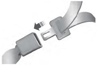
The front outboard and rear safety restraints in the vehicle are combination lap and shoulder belts.
Insert the belt tongue into the proper buckle (the buckle closest to the direction the tongue is coming from) until you hear a snap and feel it latch. Make sure that you securely fasten the tongue in the buckle.
