Lincoln Aviator 2020-2025 Service Manual / Powertrain / Engine / Engine - 3.0L EcoBoost / Removal and Installation - Cylinder Head LH
Lincoln Aviator: Engine - 3.0L EcoBoost / Removal and Installation - Cylinder Head LH
Removal
NOTICE: During engine repair procedures, cleanliness is extremely important. Any foreign material, including any material created while cleaning gasket surfaces, that enters the oil passages, coolant passages or the oil pan, can cause engine failure.
-
With the vehicle in NEUTRAL, position it on a hoist.
Refer to: Jacking and Lifting (100-02 Jacking and Lifting, Description and Operation).
-
Release the fuel system pressure.
Refer to: Fuel System Pressure Release (310-00A Fuel System - General Information - 3.0L EcoBoost, General Procedures).
-
Disconnect the battery ground cable.
Refer to: Battery Disconnect and Connect (414-01 Battery, Mounting and Cables, General Procedures).
-
Drain the cooling system.
Refer to: Engine Cooling System Draining, Vacuum Filling and Bleeding (303-03A Engine Cooling - 3.0L EcoBoost, General Procedures).
-
Remove the following items:
-
Refer to: Camshaft LH (303-01A Engine - 3.0L EcoBoost, Removal and Installation).
-
LH side.
Refer to: Cylinder Head to Coolant Outlet Connector Hose Assembly (303-03A Engine Cooling - 3.0L EcoBoost, Removal and Installation).
-
Refer to: Camshaft LH (303-01A Engine - 3.0L EcoBoost, Removal and Installation).
-
-
Loosen the fuel rail-to-fuel rail high-pressure fuel tube flare nuts.
-
Remove and discard the high-pressure fuel tube.
-
Loosen the fuel rail-to-fuel rail high-pressure fuel tube flare nuts.
.jpg) |
-
-
Remove and discard the cylinder head bolts.
-
Remove the cylinder head.
-
Remove and discard the cylinder head bolts.
.jpg) |
-
Remove and discard the cylinder head gasket.
.jpg) |
-
-
Clean and inspect the cylinder head-to-cylinder
block mating surfaces of both the cylinder head and the cylinder block.
-
Refer to: Cylinder Head Distortion (303-00 Engine System - General Information, General Procedures).
-
Refer to: Cylinder Block Distortion (303-00 Engine System - General Information, General Procedures).
-
Clean and inspect the cylinder head-to-cylinder
block mating surfaces of both the cylinder head and the cylinder block.
.jpg) |
Installation
-
Install a new cylinder head gasket.
.jpg) |
-
-
Install the cylinder head.
-
Install new cylinder head bolts.
Torque:
Stage 1: 177 lb.in (20 Nm)
Stage 2: Loosen: 2 turn(s)
Stage 3: 37 lb.ft (50 Nm)
Stage 4: 180°
-
Install the cylinder head.
.jpg) |
-
NOTE: Make sure that a new component is installed.
Install a new fuel rail-to-fuel rail high-pressure fuel tube and finger tighten the flare nuts.
-
Final tighten the flare nuts.
Torque:
Stage 1: 62 lb.in (7 Nm)
Stage 2: 89 lb.in (10 Nm)
Stage 3: 25°
-
Final tighten the flare nuts.
.jpg) |
-
Install the following items:
-
LH side.
Refer to: Cylinder Head to Coolant Outlet Connector Hose Assembly (303-03A Engine Cooling - 3.0L EcoBoost, Removal and Installation).
-
Refer to: Camshaft LH (303-01A Engine - 3.0L EcoBoost, Removal and Installation).
-
LH side.
-
Connect the battery ground cable.
Refer to: Battery Disconnect and Connect (414-01 Battery, Mounting and Cables, General Procedures).
-
Pressurize the fuel system.
Refer to: Fuel System Pressure Release (310-00A Fuel System - General Information - 3.0L EcoBoost, General Procedures).
-
Fill and bleed the cooling system.
Refer to: Engine Cooling System Draining, Vacuum Filling and Bleeding (303-03A Engine Cooling - 3.0L EcoBoost, General Procedures).
-
Use the Powertrain Control Module (PCM) Misfire Monitor Profile Correction routine in the diagnostic scan tool.
 Removal and Installation - Crankshaft Rear Seal with Retainer Plate
Special Tool(s) /
General Equipment
303-1250Seal Installer, Rear MainTKIT-2006UFFLM
Plastic Scraper
Materials
Name
Specification
Motorcraft® High Performance Engine RTV SiliconeTA-357
WSE-M4G323-A6
Motorcraft® Silicone Gasket RemoverZC-30-A
-
Motorcraft® Metal Surface Prep WipesZC-31-B
-
Motorcraft® Metal Brake Parts CleanerPM-4-A, PM-4-B
-
Removal
Remove the flexplate...
Other information:
Lincoln Aviator 2020-2025 Owners Manual: Information Display Control and Horn
I..
Lincoln Aviator 2020-2025 Service Manual: Removal and Installation - Roof Rail
Removal NOTE: Removal steps in this procedure may contain installation details. NOTE: LH side shown, RH side similar. Lower the headliner. Refer to: Headliner - Lowering (501-05 Interior Trim and Ornamentation, Removal and Installation)...
Categories
- Manuals Home
- Lincoln Aviator Owners Manual
- Lincoln Aviator Service Manual
- Anti-Theft Alarm
- Resetting the System
- Keyless Entry
- New on site
- Most important about car
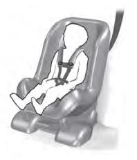
Child Seats

Use a child restraint (sometimes called an infant carrier, convertible seat, or toddler seat) for infants, toddlers and children weighing 40 lb (18 kg) or less (generally four-years-old or younger).
Using Lap and Shoulder Belts
WARNING: Do not place a rearward facing child restraint in front of an active airbag. Failure to follow this instruction could result in personal injury or death.
Copyright © 2025 www.liaviator2.com

