Lincoln Aviator: Engine - 3.0L EcoBoost / Removal and Installation - Camshaft Roller Follower
Special Tool(s) /
General Equipment
|
303-1633 Remover, Roller Rocker Follower TKIT-2014D-ROW3 TKIT-2014D-FL_ROW |
Removal
NOTICE:
During engine repair procedures, cleanliness is extremely
important. Any foreign material, including any material created while
cleaning gasket surfaces, that enters the oil passages, coolant passages
or the oil pan, can cause engine failure.
-
Remove the LH and/or RH valve covers.
Refer to: Valve Cover LH (303-01A Engine - 3.0L EcoBoost, Removal and Installation).
Refer to: Valve Cover RH (303-01A Engine - 3.0L EcoBoost, Removal and Installation).
-
Rotate the crankshaft pulley bolt clockwise to position
the camshaft lobe upward for the camshaft roller follower to be removed.
-
-
Install Special Service Tool: 303-1633
Remover, Roller Rocker Follower.
-
Turn the knob on the special tool clockwise to depress the valve and spring.
-
Unclip the camshaft roller follower from the
hydraulic lash adjuster and remove the camshaft roller follower.
Installation
-
NOTE:
Component(s) must be lubricated with clean engine oil.
-
Lubricate the camshaft roller follower with clean engine oil.
-
Position the camshaft roller follower and engage the clip onto the hydraulic lash adjuster.
-
Turn the knob on the special tool counterclockwise to raise the valve and spring.
-
Remove Special Service Tool: 303-1633
Remover, Roller Rocker Follower.
-
Install the LH and/or RH valve covers.
Refer to: Valve Cover LH (303-01A Engine - 3.0L EcoBoost, Removal and Installation).
Refer to: Valve Cover RH (303-01A Engine - 3.0L EcoBoost, Removal and Installation).
Special Tool(s) /
General Equipment
303-1633Remover, Roller Rocker FollowerTKIT-2014D-ROW3TKIT-2014D-FL_ROW
Materials
Name
Specification
Flange SealantCU7Z-19B508-A
WSS-M2G348-A11
Removal
NOTICE:
During engine repair procedures, cleanliness is extremely
important...
Special Tool(s) /
General Equipment
303-1531Installer, Front Crank Seal and Damper
303-335
(T88T-6701-A)
Installer, Front Cover Oil SealTKIT-1988-FLMTKIT-1988-F
303-409
(T92C-6700-CH)
Remover, Crankshaft SealTKIT-1992-FH/FMH/FLMHTKIT-1993-LMH/MH
Removal
Remove the crankshaft pulley...
Other information:
Special Tool(s) /
General Equipment
Boot Clamp Pliers
Materials
Name
Specification
Motorcraft® Premium Long-Life GreaseXG-1-E1
ESA-M1C75-B
Removal
NOTICE:
The steering gear boots and clamps are designed to provide
an airtight seal and protect the internal components of the steering
gear...
Diagnostic Trouble Code (DTC) Chart
Diagnostics in this manual assume a certain skill level and knowledge of Ford-specific diagnostic practices.REFER to: Diagnostic Methods (100-00 General Information, Description and Operation).
Diagnostic Trouble Code Chart
Module
DTC
Description
Action
PCM
P0300:00
Random Misfire Detected: No Sub Type Information
GO to Pinpoint Test HD
PCM
P0301:00
Cylinder 1 Misfire Detected: No Sub Type Information
GO to Pinpoint Test HD
PCM
P0302:00
Cylinder 2 Misfire Detected: No Sub Type Information
GO to Pinpoint Test HD
PCM
P0303:00
Cylinder 3 Misfire Detected: No Sub Type Information
GO to Pinpoint Test HD
PCM
P0304:00
Cylinder 4 Misfire Detected: No Sub Type Information
GO to Pinpoint Test HD
PCM
P0305:00
Cylinder 5 Misfire Detected: No Sub Type Information
GO to Pinpoint Test HD
PCM
P0306:00
Cylinder 6 Misfire Detected: No Sub Type Information
GO to Pinpoint Test HD
PCM
P0307:00
Cylinder 7 Misfire Detected: No Sub Type Information
GO to Pinpoint Test HD
PCM
P0308:00
Cylinder 8 Misfire Detected: No Sub Type Information
GO to Pinpoint Test HD
PCM
P0313:00
Misfire Detected With Low Fuel: No Sub Type Information
GO to Pinpoint Test HD
PCM
P0316:00
Misfire Detected On Startup (First 1000 Revolutions): No Sub Type Information
GO to Pinpoint Test HD
PCM
P0325:00
Knock/Combustion Vibration Sensor A Circuit: No Sub Type Information
GO to Pinpoint Test DG
PCM
P0327:00
Knock/Combustion Vibration Sensor A Circuit Low: No Sub Type Information
GO to Pinpoint Test DG
PCM
P0328:00
Knock/Combustion Vibration Sensor A Circuit High: No Sub Type Information
GO to Pinpoint Test DG
PCM
P032A:00
Knock/Combustion Vibration Sensor C Circuit: No Sub Type Information
GO to Pinpoint Test DG
PCM
P032C:00
Knock/Combustion Vibration Sensor C Circuit Low: No Sub Type Information
GO to Pinpoint Test DG
PCM
P032D:00
Knock/Combustion Vibration Sensor C Circuit High: No Sub Type Information
GO to Pinpoint Test DG
PCM
P0330:00
Knock/Combustion Vibration Sensor B Circuit: No Sub Type Information
GO to Pinpoint Test DG
PCM
P0332:00
Knock/Combustion Vibration Sensor B Circuit Low: No Sub Type Information
GO to Pinpoint Test DG
PCM
P0333:00
Knock/Combustion Vibration Sensor B Circuit High: No Sub Type Information
GO to Pinpoint Test DG
PCM
P033A:00
Knock/Combustion Vibration Sensor D Circuit: No Sub Type Information
GO to Pinpoint Test DG
PCM
P033C:00
Knock/Combustion Vibration Sensor D Circuit Low: No Sub Type Information
GO to Pinpoint Test DG
PCM
P033D:00
Knock/Combustion Vibration Sensor D Circuit High: No Sub Type Information
GO to Pinpoint Test DG
PCM
P0351:00
Ignition Coil A Primary Control Circuit/Open: No Sub Type Information
GO to Pinpoint Test JF
PCM
P0352:00
Ignition Coil B Primary Control Circuit/Open: No Sub Type Information
GO to Pinpoint Test JF
PCM
P0353:00
Ignition Coil C Primary Control Circuit/Open: No Sub Type Information
GO to Pinpoint Test JF
PCM
P0354:00
Ignition Coil D Primary Control Circuit/Open: No Sub Type Information
GO to Pinpoint Test JF
PCM
P0355:00
Ignition Coil E Primary Control Circuit/Open: No Sub Type Information
GO to Pinpoint Test JF
PCM
P0356:00
Ignition Coil F Primary Control Circuit/Open: No Sub Type Information
GO to Pinpoint Test JF
PCM
P0357:00
Ignition Coil G Primary Control Circuit/Open: No Sub Type Information
GO to Pinpoint Test JF
PCM
P0358:00
Ignition Coil H Primary Control Circuit/Open: No Sub Type Information
GO to Pinpoint Test JF
PCM
P06B6:00
Internal Control Module Knock Sensor Processor 1 Performance: No Sub Type Information
GO to Pinpoint Test DG
PCM
P06D1:00
Internal Control Module Ignition Coil Control Module Performance: No Sub Type Information
GO to Pinpoint Test JF
PCM
P112A:00
Too Many Engine Starts During Factory/Transport Mode: No Sub Type Information
GO to Pinpoint Test JB
PCM
P130D:00
Engine Knock/Combustion Performance - Forced Limited Power: No Sub Type Information
GO to Pinpoint Test DG
PCM
P2300:00
Ignition Coil A Primary Control Circuit Low: No Sub Type Information
GO to Pinpoint Test JF
PCM
P2301:00
Ignition Coil A Primary Control Circuit High: No Sub Type Information
GO to Pinpoint Test JF
PCM
P2303:00
Ignition Coil B Primary Control Circuit Low: No Sub Type Information
GO to Pinpoint Test JF
PCM
P2304:00
Ignition Coil B Primary Control Circuit High: No Sub Type Information
GO to Pinpoint Test JF
PCM
P2306:00
Ignition Coil C Primary Control Circuit Low: No Sub Type Information
GO to Pinpoint Test JF
PCM
P2307:00
Ignition Coil C Primary Control Circuit High: No Sub Type Information
GO to Pinpoint Test JF
PCM
P2309:00
Ignition Coil D Primary Control Circuit Low: No Sub Type Information
GO to Pinpoint Test JF
PCM
P2310:00
Ignition Coil D Primary Control Circuit High: No Sub Type Information
GO to Pinpoint Test JF
PCM
P2312:00
Ignition Coil E Primary Control Circuit Low: No Sub Type Information
GO to Pinpoint Test JF
PCM
P2313:00
Ignition Coil E Primary Control Circuit High: No Sub Type Information
GO to Pinpoint Test JF
PCM
P2315:00
Ignition Coil F Primary Control Circuit Low: No Sub Type Information
GO to Pinpoint Test JF
PCM
P2316:00
Ignition Coil F Primary Control Circuit High: No Sub Type Information
GO to Pinpoint Test JF
PCM
P2319:00
Ignition Coil G Primary Control Circuit High: No Sub Type Information
GO to Pinpoint Test JF
PCM
P2322:00
Ignition Coil H Primary Control Circuit High: No Sub Type Information
GO to Pinpoint Test JF
Global Customer Symptom Code (GCSC) Chart
Diagnostics in this manual assume a certain skill level and knowledge of Ford-specific diagnostic practices...
Categories
The front outboard and rear safety restraints
in the vehicle are combination lap and
shoulder belts.
Insert the belt tongue into the proper
buckle (the buckle closest to the direction
the tongue is coming from) until you hear
a snap and feel it latch. Make sure that
you securely fasten the tongue in the
buckle.
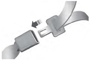
To unfasten, press the release button
and remove the tongue from the buckle.
read more