Lincoln Aviator 2020-2025 Service Manual / Electrical / Electronic Feature Group / Passive Anti-Theft System (PATS) - Vehicles With: Phone as a Key / Removal and Installation - Bluetooth Floor Console Antenna
Lincoln Aviator: Passive Anti-Theft System (PATS) - Vehicles With: Phone as a Key / Removal and Installation - Bluetooth Floor Console Antenna
Special Tool(s) / General Equipment
| Pick Hook | |
| Interior Trim Remover |
Removal
-
Remove the FCIMB.
Refer to: Front Controls Interface Module B (FCIMB) (415-00 Information and Entertainment System - General Information, Removal and Installation).
-
Remove the floor console top panel front bolts.
.jpg) |
-
NOTE: Seats removed for clarity.
On LH side.
Remove the floor console front lower trim panel.
-
Position the floor console front lower trim panel bolt cover aside.
Use the General Equipment: Pick Hook
-
Remove the floor console front lower trim panel bolt.
-
Release the clips.
Use the General Equipment: Interior Trim Remover
-
Position the floor console front lower trim panel bolt cover aside.
.jpg) |
-
NOTE: Seats removed for clarity.
On RH side.
Release the clips and remove the floor console front lower trim panel.
Use the General Equipment: Interior Trim Remover
.jpg) |
-
NOTE: Left hand side shown, right hand side similar.
NOTE: Seats removed for clarity.
On both sides.
Release the clips and remove the floor console side trim panel.
.jpg) |
-
NOTE: Left hand side shown, right hand side similar.
NOTE: Seats removed for clarity.
On both sides.
Release the clips and remove the floor console upper trim panel.
Use the General Equipment: Interior Trim Remover
.jpg) |
-
NOTE: Seats removed for clarity.
Remove the floor console side screws.
.jpg) |
-
NOTE: Seats removed for clarity.
Remove the floor console upper trim panel.
-
Release the clips.
Use the General Equipment: Interior Trim Remover
-
If equipped.
Disconnect the media hub electrical connector.
-
If equipped.
Disconnect the media hub electrical connector.
-
Disconnect the parking brake switch electrical connector.
-
If equipped.
Disconnect the ATCM electrical connector.
-
Release the clips.
.jpg) |
-
Remove the bluetooth floor console antenna.
-
Disconnect the bluetooth floor console antenna electrical connector.
-
Release the bluetooth floor console antenna clip.
Use the General Equipment: Interior Trim Remover
-
Disconnect the bluetooth floor console antenna electrical connector.
.jpg) |
Installation
-
To install, reverse the removal procedure.
-
Using the diagnostic scan tool, carry out the remote function actuator (RFA) module self test.
 Removal and Installation - Bluetooth B-Pillar Antenna
Special Tool(s) /
General Equipment
Interior Trim Remover
Removal
NOTE:
Left hand side shown, right hand side similar.
Remove the lower B-pillar trim panel...
 Removal and Installation - Bluetooth Front Exterior Antenna
Special Tool(s) /
General Equipment
Interior Trim Remover
Removal
Remove the front bumper cover.
Refer to: Front Bumper Cover (501-19 Bumpers, Removal and Installation)...
Other information:
Lincoln Aviator 2020-2025 Service Manual: Description and Operation - Anti-Lock Brake System (ABS) and Stability Control - System Operation and Component Description
System Operation System Diagrams Anti-Lock Brake System (ABS) and Stability Control Item Description 1 EBB assembly 2 ABS module 3 GWM 4 RCM 5 PSCM 6 BCM 7 AWD module 8 IPC 9 IPMA 10 FCIM 11 GSM 12 PCM 13 SODR 14 SODL 15 Brake fluid level switch 16 Hydraulic pressure sensor 17 Hydraulic pump motor 18 Hydraulic valve solenoids 19 IPMB 20 CCM 21 PAM 22 ATCM 23 Wheel speed sensors 24 SOBDMC ( HEV) 25 VDM 26 Actuator position sensor Steering Angle Sensor Module (SASM) — Vehicles With Adaptive Steering Item Description 1 Private CAN 2 SASM 3 Steering wheel rotation sensor 4 LH multifunction switch 5 RH multifunction switch 6 PSCM 7 RCM 8 SUMA 9 SECM (Adaptive Steering Only) 10 GWM 11 PCM 12 BCM 13 APIM 14 IPC 15 HVAC 16 SIMA Network Message Charts Anti-Lock Brake System (ABS) Module - Network Input Messages Module Network Input Messages - ABS Module Broadcast Message Originating Module Message Purpose Accelerator pedal position PCM This message is sent to the GWM and then to the ABS module...
Lincoln Aviator 2020-2025 Service Manual: Removal and Installation - Cruise Control Module (CCM)
Removal NOTE: Removal steps in this procedure may contain installation details. All vehicles NOTE: If installing a new CCM, it is necessary to upload the module configuration information to the scan tool prior to removing the module. This information must be downloaded into the new CCM after installation...
Categories
- Manuals Home
- Lincoln Aviator Owners Manual
- Lincoln Aviator Service Manual
- Wireless Accessory Charger (If Equipped)
- Activating Intelligent Access
- USB Port and Power Point Locations
- New on site
- Most important about car
Fastening the Seatbelts
The front outboard and rear safety restraints in the vehicle are combination lap and shoulder belts.
Insert the belt tongue into the proper buckle (the buckle closest to the direction the tongue is coming from) until you hear a snap and feel it latch. Make sure that you securely fasten the tongue in the buckle.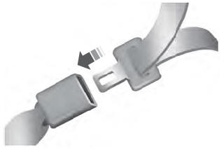
Copyright © 2025 www.liaviator2.com