Lincoln Aviator 2020-2025 Service Manual / Electrical / Information and Entertainment Systems / Information and Entertainment System - General Information / Removal and Installation - Automotive Audio Bus (AAB) Cable
Lincoln Aviator: Information and Entertainment System - General Information / Removal and Installation - Automotive Audio Bus (AAB) Cable
Removal
NOTE: Removal steps in this procedure may contain installation details.
NOTE: The original equipment AAB cable is part of the wiring harness and cannot be removed. This procedure refers to replacement of the cable only by overlaying the cable.
-
Remove the loadspace trim panels.
Refer to: Loadspace Trim Panel (501-05 Interior Trim and Ornamentation, Removal and Installation).
-
Disconnect the AAB cable connector.
.jpg) |
-
Disconnect the subwoofer electrical connector.
.jpg) |
-
Position the subwoofer assembly to access rear connectors.
-
Remove the nut.
Torque: 80 lb.in (9 Nm)
-
Remove the bolts.
Torque: 80 lb.in (9 Nm)
-
Remove the nut.
.jpg) |
-
Disconnect the electrical connectors and remove the subwoofer assembly.
.jpg) |
Installation
-
Cut the end off the existing cable.
.jpg) |
-
Cut the end off the existing cable.
.jpg) |
-
Route the new AAB following the routing shown.
-
Secure the new AAB, as necessary, to prevent NVH concerns.
-
Secure the new AAB, as necessary, to prevent NVH concerns.
.jpg) |
-
To install, reverse the removal procedure.
 Removal and Installation - Audio Unit Antenna Cable
Removal
NOTE:
Removal steps in this procedure may contain installation details.
NOTE:
The original equipment antenna cables arepart of the wiring
harnesses and cannot be removed...
 Removal and Installation - Cellular Antenna Cable
Removal
NOTE:
Removal steps in this procedure may contain installation details.
All vehicles
Lower the headliner.
Refer to: Headliner - Lowering (501-05 Interior Trim and Ornamentation, Removal and Installation)...
Other information:
Lincoln Aviator 2020-2025 Service Manual: Description and Operation - Glass, Frames and Mechanisms - System Operation and Component Description
System Operation System Diagram - Power Windows Driver Side Power Windows Item Description 1 LIN 2 Driver Side Front Window Motor 3 Driver Side Rear Window Control Switch 4 Driver Window Control Switch 5 DDM 6 Driver Side Rear Window Motor Passenger Side Power Windows Item Description 1 Passenger Front Window Motor 2 Passenger Rear Window Motor 3 Passenger Side Rear Window Control Switch 4 Passenger Side Front Window Control Switch 5 PDM 6 DDM 7 MS-CAN Network Message Chart - Power Windows Passenger Door Module (PDM) Network Input Messages Broadcast Message Originating Module Message Purpose Passenger window command DDM When activating the passenger front or rear windows from the driver window control switch, the passenger window command is sent from the DDM to the PDM...
Lincoln Aviator 2020-2025 Service Manual: Diagnosis and Testing - Acceleration Control
Diagnostic Trouble Code (DTC) Chart Diagnostics in this manual assume a certain skill level and knowledge of Ford-specific diagnostic practices.REFER to: Diagnostic Methods (100-00 General Information, Description and Operation). Diagnostic Trouble Code Chart Module DTC Description Action PCM P060D:00 Internal Control Module Accelerator Pedal Position Performance: No Sub Type Information GO to Pinpoint Test DK PCM P1575:00 Pedal Position Out Of Self Test Range: No Sub Type Information GO to Pinpoint Test DK PCM P2122:00 Throttle/Pedal Position Sensor/Switch D Circuit Low: No Sub Type Information GO to Pinpoint Test DK PCM P2123:00 Throttle/Pedal Position Sensor/Switch D Circuit High: No Sub Type Information GO to Pinpoint Test DK PCM P2127:00 Throttle/Pedal Position Sensor/Switch E Circuit Low: No Sub Type Information GO to Pinpoint Test DK PCM P2128:00 Throttle/Pedal Position Sensor/Switch E Circuit High: No Sub Type Information GO to Pinpoint Test DK PCM P2138:00 Throttle/Pedal Position Sensor/Switch D/E Voltage Correlation: No Sub Type Information GO to Pinpoint Test DK Global Customer Symptom Code (GCSC) Chart Diagnostics in this manual assume a certain skill level and knowledge of Ford-specific diagnostic practices...
Categories
- Manuals Home
- Lincoln Aviator Owners Manual
- Lincoln Aviator Service Manual
- Disabling Auto-Start-Stop
- Refueling
- Drive Modes
- New on site
- Most important about car
Fastening the Seatbelts
The front outboard and rear safety restraints in the vehicle are combination lap and shoulder belts.
Insert the belt tongue into the proper buckle (the buckle closest to the direction the tongue is coming from) until you hear a snap and feel it latch. Make sure that you securely fasten the tongue in the buckle.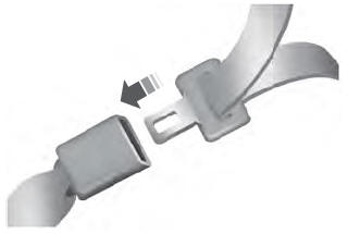
Copyright © 2025 www.liaviator2.com