Lincoln Aviator 2020-2025 Service Manual / Chassis / Suspension / Vehicle Dynamic Suspension / Removal and Installation - Air Suspension Compressor
Lincoln Aviator: Vehicle Dynamic Suspension / Removal and Installation - Air Suspension Compressor
Removal
.jpg) WARNING:
Vent all air pressure from the air suspension system prior
to disconnecting or removing any air suspension components. It is
dangerous to remove air suspension components while under pressure.
Failure to follow this instruction may result in serious personal
injury.
WARNING:
Vent all air pressure from the air suspension system prior
to disconnecting or removing any air suspension components. It is
dangerous to remove air suspension components while under pressure.
Failure to follow this instruction may result in serious personal
injury.
NOTE: Removal steps in this procedure may contain installation details.
-
If installing a new air suspension compressor, connect
the scan tool and upload the module configuration information from the SUMA.
Refer to: Module Configuration - System Operation and Component Description (418-01 Module Configuration, Description and Operation).
-
Depressurize the air suspension system.
-
Remove the RH front fender splash shield.
Refer to: Fender Splash Shield (501-02 Front End Body Panels, Removal and Installation).
-
Position the air suspension compressor assembly.
-
NOTE: The lower retainer is located toward the front of the vehicle. Limited accessibility.
Remove the retainers.
Torque: 18 lb.ft (25 Nm)
-
Position the air suspension compressor assembly down and out of the fender.
-
Support the air suspension compressor assembly using mechanics wire.
-
.jpg) |
-
Disconnect the air suspension control module electrical connector.
.jpg) |
-
NOTE: Note the position of the components before removal.
NOTE: Air lines are color coded and must be installed in the same location from which there were removed.
Disconnect the air suspension compressor assembly air lines and remove the air suspension compressor assembly.
.jpg) |
Installation
-
To install, reverse the removal procedure.
-
When installing a new air suspension compressor, it must
be configured (using vehicle as-built data or module configuration
information retrieved earlier in this procedure). Refer to the scan tool
instructions to carry out PMI.
Refer to: Module Configuration - System Operation and Component Description (418-01 Module Configuration, Description and Operation).
-
Calibrate the suspension system. Connect the scan tool
and carry out the Ride Height Calibration routine. Follow the scan tool
directions.
 General Procedures - Air Suspension System Depressurize and Pressurize
Pressure release
Assemble the following items:
Shut off valve
Pressure regulator with gauge
R-134a low side refrigerant line fitting
Air line male quick connect fitting
Position the vehicle on a hoist...
 Removal and Installation - Air Suspension Reservoir
Removal
WARNING:
Vent all air pressure from the air suspension system prior
to disconnecting or removing any air suspension components. It is
dangerous to remove air suspension components while under pressure...
Other information:
Lincoln Aviator 2020-2025 Owners Manual: Route Guidance
Turn indicator. Select to hear the last voice prompt. Point of interest. Estimated time of arrival, distance to destination or time to destination. Current road. Mute guidance prompts. Note: To change guidance prompt volume, turn the volume control when a guidance prompt plays...
Lincoln Aviator 2020-2025 Service Manual: General Procedures - Piston Ring End Gap
Special Tool(s) / General Equipment Feeler Gauge Check NOTE: Refer to the appropriate Section 303-01 for the specification. NOTE: Use care when fitting piston rings to avoid possible damage to the piston ring or the cylinder bore...
Categories
- Manuals Home
- Lincoln Aviator Owners Manual
- Lincoln Aviator Service Manual
- Drive Modes
- Disabling Auto-Start-Stop
- Opening and Closing the Hood
- New on site
- Most important about car
Fastening the Seatbelts
The front outboard and rear safety restraints in the vehicle are combination lap and shoulder belts.
Insert the belt tongue into the proper buckle (the buckle closest to the direction the tongue is coming from) until you hear a snap and feel it latch. Make sure that you securely fasten the tongue in the buckle.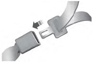
Copyright © 2025 www.liaviator2.com