Lincoln Aviator: Automatic Transmission - 10-Speed Automatic Transmission – 10R60 / Diagnosis and Testing - Preliminary Inspection
Overview
The preliminary inspection is part of Automatic Transmission Diagnosis. The preliminary inspection is used to find obvious causes of transmission concerns.
To correctly diagnose a concern, first understand the customer concern or condition. Customer contact may be required to understand the conditions, including when the concern occurs.
Underhood Inspection
-
Look for missing or damaged air induction components.
-
Inspect the wire harness for proper routing, especially near
the rear of the cylinder heads. Make sure the harness is not chafed or
pinched.
-
Inspect transmission fluid cooler for proper mounting and check for any missing air deflectors.
Under Vehicle Inspection
-
With the vehicle in NEUTRAL, position it on a hoist.
REFER to: Jacking and Lifting (100-02 Jacking and Lifting, Description and Operation).
-
Place the selector lever in D.
-
Inspect the transmission case for evidence of leaks.
-
Inspect the transmission fluid cooler lines for proper routing, pinches, or kinks.
-
Inspect the transmission fluid cooler mounting and check for any missing air deflectors.
-
Adjust the selector lever cable. (if equipped)
Transmission Fluid Inspection
Transmission fluid condition can provide many clues to the nature of the transmission concern. Proper transmission fluid level can only be determined with the transmission fluid within a specified temperature range. It is not necessary to verify exact transmission fluid level at this time. If the transmission fluid is below operating temperature, it is expected to be low on the transmission fluid level indicator. Transmission fluid temperatures below 30.2 °F ( -1 °C) may not show up on a transmission fluid level indicator.
-
With the vehicle in NEUTRAL, position it on a hoist.
REFER to: Jacking and Lifting (100-02 Jacking and Lifting, Description and Operation).
-
Remove the transmission fluid fill plug or the transmission fluid level indicator.
-
Allow the transmission fluid to drip onto a facial tissue or white sheet of paper.
-
Examine the stain. Under normal conditions, the fluid color
will darken and may develop an odor. Color and odor should not be used
to determine the condition of the fluid or transmission.
-
Trace amounts of black or shiny metallic particles may
be present from normal wear and operation. Presences of a few particles
in the sample do not necessarily indicate a transmission concern.
-
Large quantities of black particles are typically burnt friction material.
-
Large quantities of small to medium sized shiny metallic particles may indicate excessive hard part wear.
-
Foamy pink color indicates either water or engine coolant in the transmission.
-
Trace amounts of black or shiny metallic particles may
be present from normal wear and operation. Presences of a few particles
in the sample do not necessarily indicate a transmission concern.
Water in Transmission Fluid
To correctly repair an automatic transmission that has had water or coolant introduced into the system, completely disassemble, clean, and replace the following parts:
- All internal and external seals
- All friction material
- Torque converter
- All parts with bonded seals
- All solenoids
- All transmission fluid filters
Prior to installing the transmission, flush and clean the transmission fluid cooler(s) and the transmission fluid cooler tubes and hoses.
 Diagnosis and Testing - Diagnostic Strategy
Overview
The
diagnostic process for each transmission concern will vary depending on
the symptoms and condition of the vehicle. The diagnostic process
below is an efficient method to collect as much data as possible about
the concern before performing a repair or removing the transmission from
the vehicle for teardown and further inspection...
 Diagnosis and Testing - Road Testing Vehicle
Shift Point Road Test
NOTE:
Always drive the vehicle in a safe manner according to driving conditions and obey all traffic laws.
Upshift Gear Sequence
At times the 10-speed transmission may skip gears when the vehicle starts from a complete stop...
Other information:
Lincoln Aviator 2020-2025 Service Manual: Removal and Installation - Driver Knee Airbag
Removal WARNING: The following procedure prescribes critical repair steps required for correct restraint system operation during a crash. Follow all notes and steps carefully. Failure to follow step instructions may result in incorrect operation of the restraint system and increases the risk of serious personal injury or death in a crash...
Lincoln Aviator 2020-2025 Service Manual: Description and Operation - F Clutch
Overview Item Description 1 SSF 2 F clutch control valve 3 F clutch latch valve 4 F clutch apply circuit 5 F clutch piston 6 F clutch assembly 7 Ring gear No...
Categories
- Manuals Home
- Lincoln Aviator Owners Manual
- Lincoln Aviator Service Manual
- Tire Change Procedure
- Child Safety Locks
- Activating Intelligent Access
- New on site
- Most important about car
Child Seats

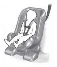
Use a child restraint (sometimes called an infant carrier, convertible seat, or toddler seat) for infants, toddlers and children weighing 40 lb (18 kg) or less (generally four-years-old or younger).
Using Lap and Shoulder Belts
WARNING: Do not place a rearward facing child restraint in front of an active airbag. Failure to follow this instruction could result in personal injury or death.
