Lincoln Aviator 2020-2025 Service Manual / Body and Paint / Body and Paint / Handles, Locks, Latches and Entry Systems / Removal and Installation - Exterior Rear Door Handle
Lincoln Aviator: Handles, Locks, Latches and Entry Systems / Removal and Installation - Exterior Rear Door Handle
Removal
NOTE: LH (left-hand) side shown, RH (right-hand) side similar.
NOTE: Removal steps in this procedure may contain installation details.
-
Remove the rear door window regulator and motor.
Refer to: Rear Door Window Regulator and Motor (501-11 Glass, Frames and Mechanisms, Removal and Installation).
-
NOTE: Rear door shown transparent for clarity.
Remove the aft rear door glass run and bracket.
-
Remove the bolts from the aft rear door glass run and bracket.
Torque: 93 lb.in (10.5 Nm)
-
Remove the aft rear door glass run and bracket.
-
Remove the bolts from the aft rear door glass run and bracket.
.jpg) |
-
NOTE: Rear door shown transparent for clarity.
Disconnect the exterior rear door handle electrical connector and position the wiring harness aside.
.jpg) |
-
Remove the exterior rear door handle reinforcement adhesive tape covers.
.jpg) |
-
NOTE: Rear door shown transparent for clarity.
Remove the exterior rear door handle and the exterior rear door handle reinforcement.
-
Remove the exterior rear door handle reinforcement nuts.
Torque: 80 lb.in (9 Nm)
-
Remove the exterior rear door handle reinforcement nut.
-
Remove the exterior rear door handle.
-
Remove the exterior rear door handle reinforcement nuts.
.jpg) |
-
Remove the exterior rear door handle gaskets.
.jpg) |
Installation
-
To install, reverse the removal procedure.
-
Carry out the power door window initialization.
Refer to: Power Door Window Initialization (501-11 Glass, Frames and Mechanisms, General Procedures).
 Removal and Installation - Exterior Front Door Handle Reinforcement
Removal
NOTE:
LH (left-hand) side shown, RH (right-hand) side similar.
NOTE:
Removal steps in this procedure may contain installation details.
Remove the front door window regulator and motor...
 Removal and Installation - Exterior Rear Door Handle Reinforcement
Removal
NOTE:
LH (left-hand) side shown, RH (right-hand) side similar.
NOTE:
Removal steps in this procedure may contain installation details.
Remove the rear door window regulator and motor...
Other information:
Lincoln Aviator 2020-2025 Service Manual: Description and Operation - Passive Anti-Theft System (PATS) - Overview
Overview NOTE: This section only describes and diagnosis the Phone as a Key system. In order for the Phone as a Key system to operate, the PATS system must be functioning correctly. For more information about the PATS system Refer to: Passive Anti-Theft System (PATS) - System Operation and Component Description (419-01B Passive Anti-Theft System (PATS), Description and Operation)...
Lincoln Aviator 2020-2025 Service Manual: General Procedures - Differential Fluid Level Check
Materials Name Specification Motorcraft® SAE 75W-140 Synthetic Rear Axle LubricantXY-75W140-QL WSL-M2C192-A Check With the vehicle in NEUTRAL, position it on a hoist. Refer to: Jacking and Lifting (100-02 Jacking and Lifting, Description and Operation)...
Categories
- Manuals Home
- Lincoln Aviator Owners Manual
- Lincoln Aviator Service Manual
- Refueling
- Anti-Theft Alarm
- Opening and Closing the Hood
- New on site
- Most important about car
Fastening the Seatbelts
The front outboard and rear safety restraints in the vehicle are combination lap and shoulder belts.
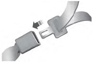
Insert the belt tongue into the proper buckle (the buckle closest to the direction the tongue is coming from) until you hear a snap and feel it latch. Make sure that you securely fasten the tongue in the buckle.
Copyright © 2025 www.liaviator2.com
