Lincoln Aviator: Rear Disc Brake / Removal and Installation - Brake Caliper
Removal
.jpg) WARNING:
Service actions on vehicles equipped with electronic brake
booster and electronic parking brakes may cause unexpected brake
application, which could result in injury to hands or fingers. Put the
brake system into service mode prior to servicing or removing any brake
components. Failure to follow this instruction may result in serious
personal injury.
WARNING:
Service actions on vehicles equipped with electronic brake
booster and electronic parking brakes may cause unexpected brake
application, which could result in injury to hands or fingers. Put the
brake system into service mode prior to servicing or removing any brake
components. Failure to follow this instruction may result in serious
personal injury.
NOTICE: Make sure that all openings are sealed.
NOTICE: If the fluid is spilled on the paintwork, the affected area must be immediately washed down with cold water.
NOTE: Removal steps in this procedure may contain installation details.
-
Activate the brake service mode.
Refer to: Brake Service Mode Activation and Deactivation (206-00 Brake System - General Information, General Procedures).
-
Remove the wheel and tire.
Refer to: Wheel and Tire (204-04A Wheels and Tires, Removal and Installation).
-
Disconnect the EPB actuator motor electrical connector.
.jpg) |
-
Remove the brake caliper flow bolt, washers and position the brake hose aside. Discard the washers.
Torque: 26 lb.ft (35 Nm)
.jpg) |
-
Remove the bolts and the brake caliper.
Torque: 26 lb.ft (35 Nm)
.jpg) |
-
Remove and discard the brake pads.
.jpg) |
-
Remove the bolts and the parking brake actuator motor. Discard the bolts.
Torque: 97 lb.in (11 Nm)
.jpg) |
Installation
-
Install the brake pads.
Refer to: Brake Pads (206-04 Rear Disc Brake, Removal and Installation).
-
NOTICE: Make sure that the brake hose is not twisted when installing the brake caliper or damage to the brake flexible hose may occur.
NOTICE: Do not damage the O-ring when installing the parking brake actuator motor to the brake caliper housing.
To install, reverse the removal procedure.
-
Deactivate the brake service mode.
Refer to: Brake Service Mode Activation and Deactivation (206-00 Brake System - General Information, General Procedures).
-
Bleed the brake system.
Refer to: Brake System Pressure Bleeding (206-00 Brake System - General Information, General Procedures).
 Removal and Installation - Brake Caliper Anchor Plate
Removal
NOTE:
Removal steps in this procedure may contain installation details.
Remove the brake pads.
Refer to: Brake Pads (206-04 Rear Disc Brake, Removal and Installation)...
Other information:
Lincoln Aviator 2020-2025 Service Manual: Description and Operation - Parking Aid - Overview
Overview - Active Park Assist The active park assist system is a full-assisted parking system. The system assists parking into and out (assist out of parking spots only available for parallel parking) of parking spaces. Sensors are used to detect parking spaces...
Lincoln Aviator 2020-2025 Owners Manual: Operating ALL-Wheel drive (AWD) Vehicles with Mismatched Tires
WARNING: Only use replacement tires and wheels that are the same size, load index, speed rating and type (such as P-metric versus LT-metric or all-season versus all-terrain) as those originally provided by Ford. The recommended tire and wheel size may be found on either the Safety Compliance Certification Label (affixed to either the door hinge pillar, door-latch post, or the door edge that meets the door-latch post, next to the driver's seating position), or the Tire Label which is located on the B-Pillar or edge of the driver's door...
Categories
- Manuals Home
- Lincoln Aviator Owners Manual
- Lincoln Aviator Service Manual
- Garage Door Opener
- Changing the Front Wiper Blades - Vehicles With: Heated Wiper Blades
- Anti-Theft Alarm
- New on site
- Most important about car
Fastening the Seatbelts
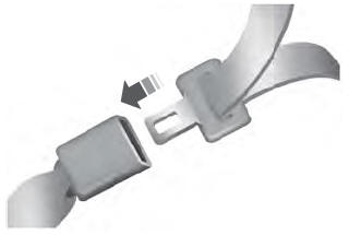
The front outboard and rear safety restraints in the vehicle are combination lap and shoulder belts.
Insert the belt tongue into the proper buckle (the buckle closest to the direction the tongue is coming from) until you hear a snap and feel it latch. Make sure that you securely fasten the tongue in the buckle.

