Lincoln Aviator: Rear Occupant Alert System / Rear Occupant Alert System Precautions and Limitations
Rear Occupant Alert System Precautions
WARNING: On hot days, the temperature inside the vehicle can rise very quickly. Exposure of people or animals to these high temperatures for even a short time can cause death or serious heat related injuries, including brain damage. Small children are particularly at risk.
WARNING: Do not leave children or pets unattended in your vehicle. Failure to follow this instruction could result in personal injury or death.
Rear Occupant Alert System Limitations
The system does not detect the presence of objects or passengers in the rear seat. It monitors when rear doors are opened and closed.
Note: It is possible to receive an alert when there is no rear seat occupant, but alert conditions are met.
Note: It is possible to receive no alert when there is an occupant in the rear seat, if alert conditions are not met. For example, if a rear seat occupant does not enter the vehicle through a rear door.
Note: The audible warning does not sound when the front door is opened before you switch the ignition off.
 How Does the Rear Occupant Alert System Work
The system monitors when rear doors have
been opened and closed to indicate the
potential presence of an occupant in the rear
seat.
A message displays in the information and
entertainment display screen and an audible
warning sounds when you switch the ignition
off after any of the following conditions have
been met:
A rear door is opened or closed while
the ignition is on...
 Switching Rear Occupant Alert System On and Off
Press Settings on the touchscreen.
Press Vehicle.
Switch Rear Occupant Alert on or off.
Note: Performing a master reset causes the
system to switch on again...
Other information:
Lincoln Aviator 2020-2026 Owners Manual: How Temperature Affects Your Tire Pressure
The tire pressure monitoring system monitors tire pressure in each pneumatic tire. While driving in a normal manner, a typical passenger tire inflation pressure may increase about 2–4 psi (14–28 kPa) from a cold start situation. If the vehicle is stationary overnight with the outside temperature significantly lower than the daytime temperature, the tire pressure may decrease about 3 psi (21 kPa) for a drop of 30°F (17°C) in ambient temperature...
Lincoln Aviator 2020-2026 Service Manual: Removal and Installation - Engine Front Cover
Special Tool(s) / General Equipment 303-050 (T70P-6000) Lifting Bracket, Engine 303-F070Support Bar, EngineTKIT-1999A-F/LTTKIT-1999A-FM/FLM Plastic Scraper Hose Clamp Remover/Installer Flat-Bladed Screwdriver Materials Name Specification Motorcraft® High Performance Engine RTV SiliconeTA-357 WSE-M4G323-A6 Motorcraft® Metal Brake Parts CleanerPM-4-A, PM-4-B - Removal NOTICE: During engine repair procedures, cleanliness is extremely important...
Categories
- Manuals Home
- Lincoln Aviator Owners Manual
- Lincoln Aviator Service Manual
- Description and Operation - Body and Frame
- Garage Door Opener
- Tire Change Procedure
- New on site
- Most important about car
Child Seats
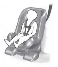
Use a child restraint (sometimes called an infant carrier, convertible seat, or toddler seat) for infants, toddlers and children weighing 40 lb (18 kg) or less (generally four-years-old or younger).
Using Lap and Shoulder Belts
WARNING: Do not place a rearward facing child restraint in front of an active airbag. Failure to follow this instruction could result in personal injury or death.