Lincoln Aviator: Body Closures / General Procedures - Rear Door Alignment
Adjustment
NOTE:
Removal steps in this procedure may contain installation details.
NOTE:
LH side shown, RH side similar.
All alignments
-
Open the rear door.
-
Remove the bolts and the striker assembly.
Torque:
18 lb.ft (25 Nm)
Rear door in and out, up and down alignment
-
Loosen the bolts to permit movement of the door.
Loosen:
:
2 turn(s)
-
Adjust the door as required.
-
Tighten the bolts.
Torque:
35 lb.ft (48 Nm)
Rear door fore, aft and tilt alignment
-
Depower the SRS.
Refer to: Supplemental Restraint System (SRS) Depowering (501-20B Supplemental Restraint System, General Procedures).
-
Remove the front seatbelt retractor and pretensioner.
Refer to: Front Seatbelt Retractor and Pretensioner (501-20A Seatbelt Systems, Removal and Installation).
-
Open the front door.
-
Pull and remove the foam.
-
Loosen the nuts to permit movement of the door.
Loosen:
:
2 turn(s)
-
Carefully close the rear door.
-
Loosen the bolt to permit movement of the door.
Loosen:
:
2 turn(s)
-
Carefully close the front door.
-
Adjust the door as required.
-
Carefully open the front door.
-
Carefully open the rear door.
-
Tighten the nuts.
Torque:
26 lb.ft (35 Nm)
-
Install the foam.
-
Tighten the bolt.
Torque:
89 lb.in (10 Nm)
-
Install the front seatbelt retractor and pretensioner.
Refer to: Front Seatbelt Retractor and Pretensioner (501-20A Seatbelt Systems, Removal and Installation).
-
Repower the SRS.
Refer to: Supplemental Restraint System (SRS) Repowering (501-20B Supplemental Restraint System, General Procedures).
-
Check the active restraint system for correct operation.
Refer to: Seatbelt Systems (501-20A Seatbelt Systems, Diagnosis and Testing).
All alignments
-
Install the striker assembly.
Torque:
18 lb.ft (25 Nm)
-
Loosen the bolts to permit movement of the striker assembly.
Loosen:
:
2 turn(s)
-
Tighten the bolts.
Torque:
18 lb.ft (25 Nm)
-
Inspect the body-to-rear door alignment.
Initialization
Disconnect the battery or remove the RGTM fuse(s).
Refer to: Battery Disconnect and Connect (414-01 Battery, Mounting and Cables, General Procedures)...
Removal
NOTE:
Removal steps in this procedure may contain installation details.
NOTE:
LH side shown, RH side similar.
Open the door...
Other information:
Removal
NOTE:
The rear heater core outline is installed from the factory
as a one-piece assembly. The replacement part is supplied as an
assembly, containing the rear heater core inlet line and the rear
evaporator inlet and outlet lines.
Remove the rear evaporator rear outlet and inlet line...
System Operation
System Diagram - Heated/Ventilated Seats
Item
Description
1
RACM
2
MS-CAN
3
SCMF
4
LH Rear Seat
5
Cushion Temp Sensor
6
RH Rear Seat
7
Backrest Heater Mat
8
Cushion Heater Mat
9
Cushion and Backrest Blower Motors
10
Backrest Heater Mat
11
Cushion Heater Mat
12
Cushion Temp Sensor
13
Cushion and Backrest Blower Motors
14
HS-CAN3
15
GWM
Network Message Chart - Heated/Ventilated Seats
SCMF (rear seat climate control module) Network Input Messages
Broadcast Message
Originating Module
Message Purpose
Seat control requests
RACM control module
Contains the heated/ventilated seat request information...
Categories
The front outboard and rear safety restraints
in the vehicle are combination lap and
shoulder belts.
Insert the belt tongue into the proper
buckle (the buckle closest to the direction
the tongue is coming from) until you hear
a snap and feel it latch. Make sure that
you securely fasten the tongue in the
buckle.
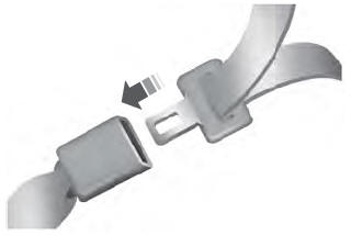
To unfasten, press the release button
and remove the tongue from the buckle.
read more
.jpg)
.jpg)
.jpg)
.jpg)
.jpg)
.jpg)
.jpg)
.jpg)
.jpg)
.jpg)
.jpg)
.jpg)
.jpg)
.jpg)
.jpg)
.jpg)
.jpg)
.jpg)
.jpg)
 General Procedures - Power Liftgate Initialization
 Removal and Installation - Front Door