Lincoln Aviator: Navigation (If Equipped) / SiriusXM Traffic and Travel Link (If Equipped)
SiriusXM Traffic and Travel Link is available on vehicles equipped with navigation and only in select markets. You must activate and subscribe to receive SiriusXM Traffic and Travel Link information. It helps you locate the best gas prices, find movie listings, get current traffic alerts, view the weather map, get accurate ski conditions and see current sports scores.
The system calculates a reasonable efficient route based on available speed limits, traffic, and road conditions. You may know a local short cut that is more efficient at a given time than the route provided by SYNC 3, but you should expect a slight difference in minutes or miles with the SYNC 3 route.
 Route Guidance
Turn indicator. Select to hear the
last voice prompt.
Point of interest.
Estimated time of arrival, distance
to destination or time to
destination...
 Michelin Travel Guide (If Equipped)
The Michelin travel guide is a service which
provides additional information about certain
places of interest, for example restaurants,
hotels and tourist sites...
Other information:
Lincoln Aviator 2020-2026 Service Manual: Removal and Installation - Air Distribution Door Actuator
Removal Fully lower the glove compartment. Disconnect the check strap. Push the stop tabs inward. Remove the screws and the air distribution door actuator. Disconnect the electrical connector...
Lincoln Aviator 2020-2026 Service Manual: Description and Operation - Second Row Climate Control - Overview
Overview The second row climate control system has components located in the center lower section of the climate control housing and floor console. The temperature and controls breakdown for the HVAC system is as follows, the first row driver, first row passenger, second row seating temperature and third row seating temperature...
Categories
- Manuals Home
- Lincoln Aviator Owners Manual
- Lincoln Aviator Service Manual
- Changing the Front Wiper Blades - Vehicles With: Heated Wiper Blades
- Configuring The Head Up Display
- Drive Modes
- New on site
- Most important about car
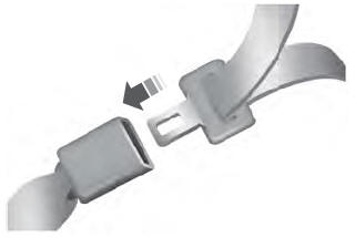
Fastening the Seatbelts
The front outboard and rear safety restraints in the vehicle are combination lap and shoulder belts.
Insert the belt tongue into the proper buckle (the buckle closest to the direction the tongue is coming from) until you hear a snap and feel it latch. Make sure that you securely fasten the tongue in the buckle.