Lincoln Aviator: Rear Drive Halfshafts / Diagnosis and Testing - Rear Drive Halfshafts
Preliminary Inspection
-
Visually inspect the CV joints, housing, boots, and clamps for obvious signs of mechanical damage.
-
If an obvious cause for an observed or reported concern is
found, correct the cause (if possible) before proceeding to the next
step
-
If the cause is not visually evident, verify the symptom and REFER to Symptom Chart: NVH.
Symptom Chart(s)
Diagnostics in this manual assume a certain skill level and knowledge of Ford-specific diagnostic practices.
REFER to: Diagnostic Methods (100-00 General Information, Description and Operation).
Symptom Chart: NVH
Symptom Chart
| Condition | Possible Sources | Actions |
|---|---|---|
| Driveline clunk - loud clunk when shifting from REVERSE to DRIVE |
|
|
|
|
|
| Driveline clunk — occurs as the vehicle starts to move forward following a stop |
|
|
| Grunting — normally associated with a shudder experienced during acceleration from a complete stop |
|
|
| Driveline vibration - occurs at cruising speeds |
|
|
Differential Seals
NOTICE: When installing shafts, do not allow splines to contact seals during installation or damage to the seals may occur.
Halfshaft seals are susceptible to the same types of damage as drive pinion seals if incorrectly installed. The seal bore must be clean and the lip handled carefully to avoid cutting or tearing it. The seal journal surface must be free of nicks, gouges and rough surface texture.
For information on differential seals,
REFER to: Rear Halfshaft Seal (205-02 Rear Drive Axle/Differential, Removal and Installation).

 Removal and Installation - Rear Halfshaft
Removal
NOTICE:
Never pick up or hold the halfshaft by only the inner or outer CV joint. Damage to the CV joint will occur.
NOTICE:
Never use a hammer to remove or install the halfshafts...
Other information:
Lincoln Aviator 2020-2025 Service Manual: Removal and Installation - Passenger Side Temperature Door Actuator
Removal Fully lower the glove compartment. Disconnect the check strap. Push the stop tabs inward. Remove the scres and the passenger side tempreature door actuator. Disconnect the electrical connector...
Lincoln Aviator 2020-2025 Owners Manual: Post-Crash Alert System
The system flashes the direction indicators and sounds the horn (intermittently) in the event of a serious impact that deploys an airbag (front, side, side curtain or Safety Canopy) or the seatbelt pretensioners. The horn and indicators turn off when: You press the hazard control button...
Categories
- Manuals Home
- Lincoln Aviator Owners Manual
- Lincoln Aviator Service Manual
- Body and Paint
- Resetting the System
- USB Port and Power Point Locations
- New on site
- Most important about car
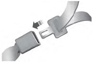
Fastening the Seatbelts
The front outboard and rear safety restraints in the vehicle are combination lap and shoulder belts.
Insert the belt tongue into the proper buckle (the buckle closest to the direction the tongue is coming from) until you hear a snap and feel it latch. Make sure that you securely fasten the tongue in the buckle.